Postion: Home > Our Case > Metal Fabrication >

 CATEGORIES
The manufacturing & design guide
Looking for high-quality sheet metal fabrication services? Look no further than our expert team! Our skilled craftsmen have years of experience in designing and creating precision sheet metal products to meet your specific needs.
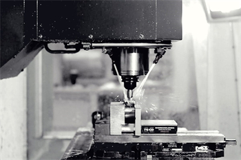
Whether you need custom prototypes or large-scale production runs, we have the expertise and equipment to deliver the results you demand. Our state-of-the-art facilities feature the latest CNC machines, laser cutters, and other advanced tools to ensure the highest levels of accuracy and efficiency.
So why wait? Contact us today to get started on your next sheet metal project. Our team is ready and waiting to help you design and manufacture the perfect product to meet your needs, on time and within budget. Don't settle for anything less than the best – trust our team to deliver the quality and precision you deserve!
The basics
Get an introduction to sheet metal fabrication. This section explains the sheet metal fabrication process, how precision sheet metal fabrication differs, the main advantages and disadvantages, as well as its common applications.
How does sheet metal fabrication work?
There are several different ways to shape sheet metal, but they all boil down to two broad categories: sheet metal can either be cut or formed.
As there are many different ways of cutting and forming sheet metal, many specific tooling types are needed which can drive up costs. This is why developing a good understanding of the various sheet metal fabrication processes available is essential to producing the most efficient design for a particular application is essential.
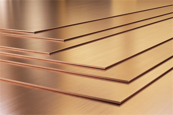
The most basic form of sheet metal fabrication begins with a flat sheet of metal and a blueprint (usually a DXF or CAD file). This blueprint will serve as the instructions on how to cut, form, and finish the base material.
It could be as simple as a single bend to turn it into angle iron, or laser cut and bent at the edges to make computer enclosure panels. When these processes are combined, the material is first cut and later formed, followed by finishing and joining.
What is precision sheet metal fabrication?
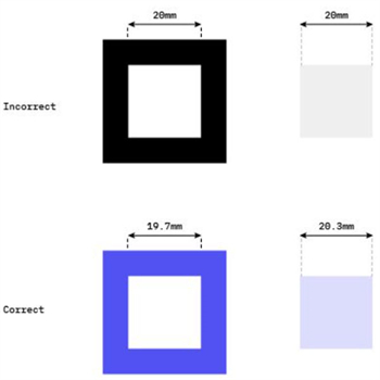
Precision sheet metal fabrication refers to some of the exact same methods and techniques as “non-precision” but to a closer degree of tolerance. This will sometimes take the design engineer more time to look at the material properties, stretch calculations, grain direction, and other in-depth research in order to obtain the precision needed.
Benefits and limitations of sheet metal fabrication
As the term sheet metal fabrication covers a wide range of processes and techniques, the advantages and disadvantages very much vary depending on the process. Below is a general snapshot of the benefits and drawbacks of fabricating sheet metal, but to have a more complete understanding of whether a particular sheet metal fabrication process is suitable for your application, more research into each individual process is needed.
Part 1
Benefits
Fast, affordable, and high quality for production or prototyping
Fabrication can quickly produce prototype parts with the same precision and speed that it can produce in production. It can also be easily customized, so if the first design doesn't work as planned - no sweat - the very next part can be adjusted. This customization aspect makes sheet metal versatile, flexible, and affordable when it comes to custom part creation.
When parts approach high volumes, sheet metal becomes even cheaper per-part with exceptionally consistent results.
Vast number of techniques and materials
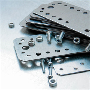
In this article alone, fourteen types of sheet metal fabrication are mentioned. These varying techniques allow make it possible to create relatively complex parts by cutting flat sheets, bending parts into place and adding holes, slots, and notches cut in all the right places.
Together with the wide range of compatible materials and its ability to withstand (even thrive) in high heat, thermal conduction, electrical, and corrosive environments, sheet metal can be suitable for a diverse number of applications.
Sheet metal can be useful when trying to keep a project lightweight. Adding bends to sheet metal increases the structure's strength tremendously because it increases the stiffness in multiple axes. Adding a finish to the sheet metal can also make the material resistant to corrosion and scratches.
Limitations
Capability limits per technique
Each technique has limits that make combining different processes a necessity. This can be an advantage, but it can also create longer processing times. For example, a laser cutter cannot make tiny holes, so a drilling or punching process would have to be included.
Bending can be a convenient operation since 3D parts can be created from flat sheets. However, it can also be very complex due to the calculations or trial-and-error aspect of the design cycle. If hole and shaft alignment is necessary, it's not always straightforward.
Part 2
Types of sheet metal fabrication
In this section, we'll cover and compare fourteen different types of sheet metal fabrication including cutting, forming, stamping, holemaking and threading.
There are numerous ways of effectively cutting through sheet metal. This section will briefly cover the many different approaches to cut through sheet metal, split into two key groups: cutting with and without shear forces.
Cutting - without shear
Several processes including extreme heat, vaporization, and high pressure abrasive blasting, make it possible to cut through sheet metal without shear. In this section, we'll cover three main types: laser cutting, plasma cutting and water jet cutting.
Plasma cutting
Plasma cutting works in roughly the same way in laser cutting, but is usually used on thicker pieces of metal where the surface finish is not as important. The plasma cutter can only be used on electrically conductive materials and works by creating an electrically charged beam of compressed ionized gas, which is known as the plasma.
The plasma is then shot through the cutter into the sheet metal and back to the grounding clamp to form a complete circuit. The material heats substantially and melts away while the compressed gas blows the excess material away. The result is a rough cut that has a large burr and oxidized zone around the cut.
Water jet cutting can be a good alternative to laser cutting, but it can be much slower. Also, laser cutting has some extra advantages because it can engrave and part mark using its depth control functionality, where water jet cutting cannot. Water jet also has a larger kerf width of 0.02-0.04” (0.5-1mm) which is much larger than a laser.
Shearing is a process where the material is cut by a shearing force that overcomes the material's ultimate shear strength. There is usually a die that holds and supports the material. At the same time, a punch or shear presses down where the die has an opening for the material to be cut through, thus cutting the part.
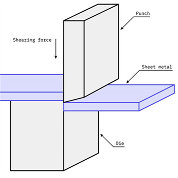
A cut achieved through shearing is different from one that uses another process. The beginning of the cut has a rollover, which leads to plastic deformation of the material from the shear force applied to it. The material then starts to burnish from stretching and rolling against the punch. The shear stress then becomes too much for the material to undergo and the material begins to fracture at a slight angle. There will also be a burr at the bottom of the material due to the material stretching at the beginning of the cut.
Cutting types - with shear
Shearing
Shearing is typically a process that involves cutting a straight line through the material and separating it into two separate pieces. It is similar to the straight edge paper cutting machine that is in most offices.
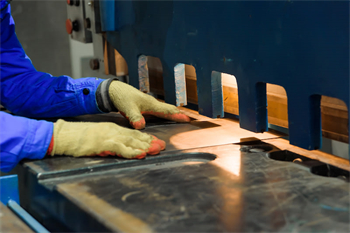
This process is usually used in order to obtain straight edges on a sheet of metal that has uneven or rough edges. This machinery uses hand power, hydraulics, electricity, or pneumatics depending on the thickness of material and length of the cut needed. The sheet of metal is placed on the die and support arms when the upper blade or punch places a large shearing force onto the material and cuts it. There is a small clearance between the die and the upper blade of about 5-10% of the sheet thickness in order to leave room for plastic deformation and fracture to occur properly.
Ideal application: High volume operations. Straight line cuts for softer materials that do not require a clean finish.
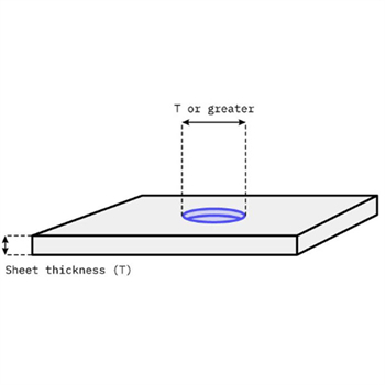
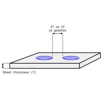
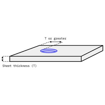
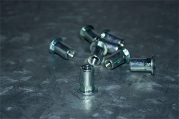
Blanking and punching
Blanking and punching are essentially the same process with opposing results. Blanking is the process where the sheet metal is held by a die and a punch places a “blanking force” through the material. The material that is punched through is the resulting component where the material still on the die is the remaining blank stock.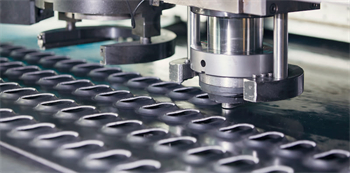
Punching is the exact opposite where the material that was punched through is scrap and the material still on the die is the resulting component.
Ideal application: Medium to high volume operations to create same shaped holes. Finish required to remove burrs.
Sawing
There are many different types of sawing operations that can be done to cut large pieces of tube or sheet.
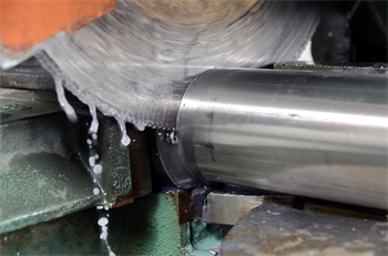
Whether a band saw or another form of saw that uses a disc saw blade, they work by progressively cutting through the material using a sawtooth tool which makes a series of hundreds of small shear cuts on the material. Each tooth on the saw separates a small chip of material away from the material body through friction and shear forces.
Ideal application: Larger workpieces made from softer metals, where tolerance and finish is important. Can produce heavy burrs.
Forming sheet metal
During the fabrication process, the sheet metal is usually first punched and cut in different ways and then followed by forming processes to make a nearly finished and realized product. Entire product chassis can be made in this way.
Not only is forming metal convenient, it also adds strength and stiffness to an assembly. In this section, we cover seven different ways to form sheet metal.
Forming types
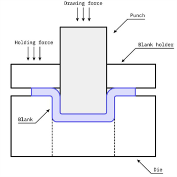
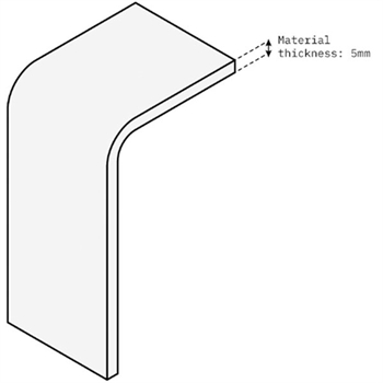
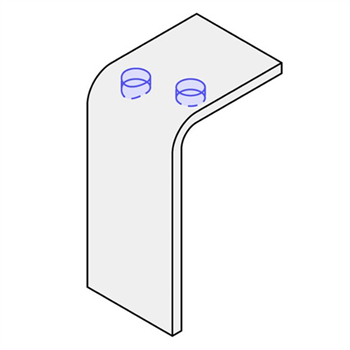
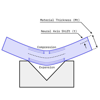
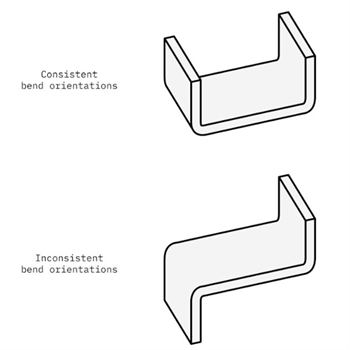
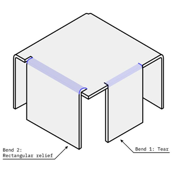
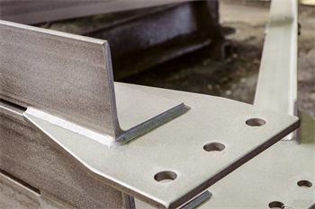
Bending
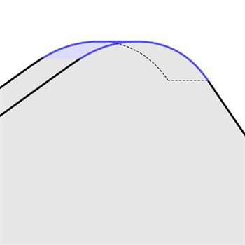
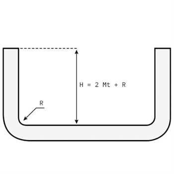
A process where a piece of sheet metal is placed onto a die with a specific geometry and the punch presses into the material to form the sheet metal to the die. Bending sounds easy and straightforward but it can be more complex than expected. For example, if the desired bend is a standard rounded corner, a 45° V-die is used. The material does not reach the inside of the V due to the thickness of the material and instead has a bend radius.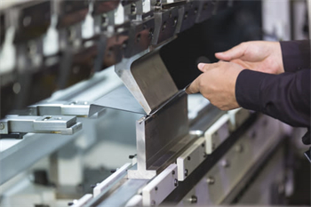
we offers sheet metal bending procedures using U-shape dies, V-shaped dies, or channel shape along the straight axis in more ductile materials.
Hemming
Hemming can be a very useful technique when shearing processes are not available but a nice straightedge without burrs is necessary. Hemming bends the sheet metal upon itself like the hem on pant legs so that the exposed edge is a rounded feature to make the interior of the sheet metal seem like an exterior edge.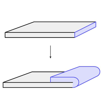
Hemming is at least a two stage process where a piece of sheet metal is bent and bottomed out into a V-die, then removed and placed into a flattening die to flatten the hem. Hemming is different from a curl because the raw edge is exposed.
Curling
Curling can also be a convenient process for a similar reason to hemming. It creates a nice rounded edge, but with curling the rough edge of the material is completely encapsulated within the curl. It can also be used for hinging applications.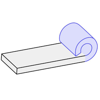
Curling usually requires three steps in total where a piece of sheet metal is pressed into a circular die in two locations, then closed together with a circular punch.
Rolling
Rolling sheet metal can be a single stage process where a thicker piece of sheet metal goes through as low as 2 (or as high as 20) hydraulically loaded rollers and compresses the sheet metal into a thinner sheet. If it goes through two or more rollers directly perpendicular to the sheet metal, the material is flattened to thinner material. With the usage of more rollers in different geometry and distances from each other the material can be shaped into different shapes.
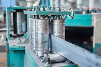
Roll forming
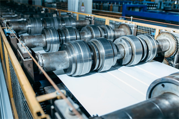
Roll forming can create long sections of complex geometries. Roll forming takes a long piece of sheet metal, usually stock comes from a spool, and goes through a series of roll dies that gradually bend the sheet stock into a progressively more intricate shape. This process leads to different types of tubing such as square and cylindrical tubing, or different types of channeling such as U-channel or other complex shapes.
Metal spinning
Metal spinning consists of a disk or cylinder of sheet metal that is placed onto a mandrel on a lathe and a roller tool shapes the sheet to the mandrel shape.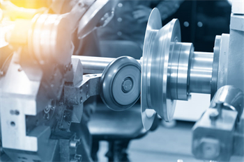

Prev: Cutting Service

Contact us and just send us your drawing (SolidWorks,ProE,CAD,PDF,DXF...)
Links: Metal Stamping Services | Sheet Metal Fabrication Services | precision cnc machining and milling services | Metal Welding Services | metal Cutting Services | Metal Bending Service | Sheet Metal Enclosure Fabrication | Surface Finishing |


![]()
![]()
